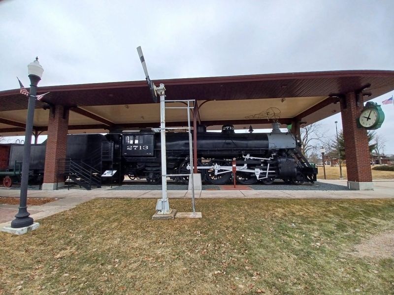
Stevens Point in Portage County, Wisconsin — The American Midwest (Great Lakes)
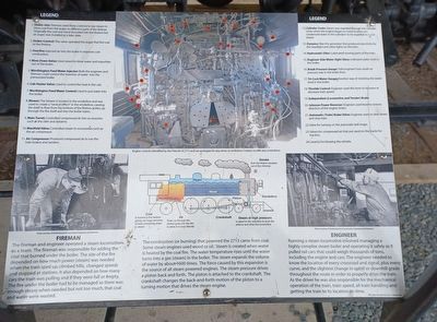
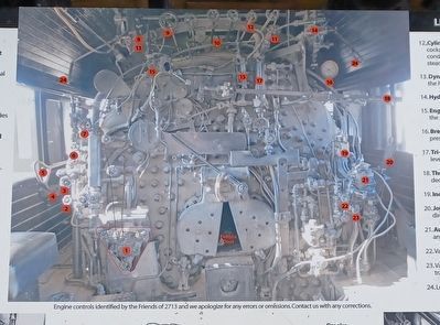
Engine 2713 Controls and Operation
Legend
- Stoker Jets: Fireman used these controls to use steam to blow coal from the auger to different parts of the firebox. Originally the coal was hand shoveled into the firebox but an auger was installed at a later date.
- Stoker Control: This valve operated the auger that fed coal to the firebox.
- Overfire: Injected air into the boiler to improve coal combustion.
- Blow Down Valve: Used steam to blow water and impurities out of the boiler.
- Worthington Feed Water Injector: Both the engineer and fireman could control the insertion of water into the pressurized boiler.
- Cab Heater Valve: Used to control the heat in the cab.
- Worthington Feed Water Control: Used to put water into the boiler.
- Blower: The blower is located in the smokebox and was used to create a "venturi effect" in the smokebox, causing the draft to flow from the bottom of the firebox grates, up through the fire itself and into the boiler tubes.
- Main Turret: Controlled steam to accessories such as the air compressor.
- Manifold Valve: Controlled steam to accessories such as the air compressor.
- Air Compressor: Produced compressed air to run the train brakes and sanders.
- Cylinder Cocks: Steam was expelled through the cylinder cocks when the engine began to move to allow any condensed water in the cylinders to be expelled with the steam.
- Dynamo: Was the generator that produced electricity for the headlight and other lights on the train.
- Hydrostatic Oiler: Lubricated moving parts of the train.
- Engineer Side Water Sight Glass: Indicated water level in the boiler.
- Break Pressure Gauge: Told engineers how much air pressure was in the brake.
- Tri-Cock Water Gauge: Another way of checking the water level in the boiler.
- Throttle Control: Engineer used this lever to increase or decrease train speed.
- Independent (Locomotive and Tender) Brake
- Johnson Power Reverser: Engineer used lever to reverse direction of the engine (train).
- Automatic (Train) Brake Valve: Engineer used to slow down and stop train.
- Valve for turning on the automatic bell ringer.
- Valves for compressed air that put sand on the tracks for traction.
- Levers for blowing the whistle.
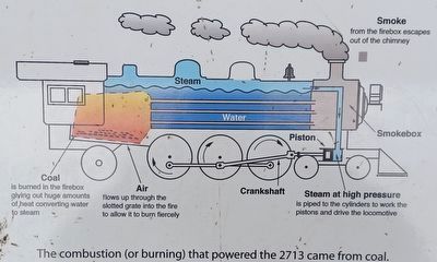
that powered the 2713 came from coal. Some steam engines used wood or oil. Steam is created when water is heated by the coal fire. The water temperature rises until the water turns into a gas (steam) in the boiler. The steam expands the volume of water by about 1600 times. The force created by this expansion is the source of all steam powered engines. The steam pressure drives a piston back and forth. The piston is attached to the crankshaft. The crankshaft changes the back-and-forth motion of the pistion to a turning motion that drives the steam engine.
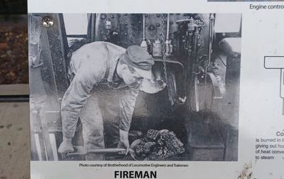
Fireman
The fireman and engineer operated a steam locomotive as a team. The fireman was responsible for adding the coal that burned under the boiler. The size of the fire depended on how much power (steam) was needed when the train sped up, climbed hills, changed speeds and stopped at stations. It also depended on how many cars the train was pulling and if they were full or empty. The fire under the boiler had to be managed so there was enough steam when needed but not too much, that coal and water were wasted.
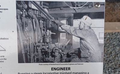
Engineer
Running a steam locomotive involved managing a highly complex steam boiler and operating it safely as it pulled cars that could weigh thousands of tons, including the engine and cars. The engineer needed to know the location of every crossroad and
signal, plus everycurve, and the slightest change in uphill or downhill grade throughout the route in order to properly drive the train. As the driver he was also responsible for the mechanical operation of the train, train speed, all train handling and getting the train to its location on time.
This sign donated by Lois Sadogierski
Topics. This historical marker is listed in this topic list: Railroads & Streetcars.
Location. 44° 30.825′ N, 89° 34.396′ W. Marker is in Stevens Point, Wisconsin, in Portage County. Marker is at the intersection of Monroe Street and Church Street (Business U.S. 51), on the right when traveling east on Monroe Street. Touch for map. Marker is in this post office area: Stevens Point WI 54481, United States of America. Touch for directions.
Other nearby markers. At least 8 other markers are within walking distance of this marker. The Historic Southside Railroad Complex of Stevens Point (a few steps from this marker); WWI Memorial (within shouting distance of this marker); Veterans World War I Memorial (within shouting distance of this marker); Stevens Point Women's Club (about 300 feet away, measured in a direct line); Portage County Civil War Memorial (approx. 0.6 miles away); First Public Building (approx. 0.8 miles away); The Boy with the Leaking Boot (approx.
4. Engine 2713 Controls and Operation Marker — middle image
Coal is burned in the firebox giving out huge amounts of heat converting water to steam.
Air flows up through the slotted grate into the fire to allow it to burn fiercely
Water
Steam
Crankshaft
Pison
Steam at high pressure is piped to the cylinders to work the pistons and drive the locomotive
Smokebox
Smoke from the firebox escapes out of the chimney
Air flows up through the slotted grate into the fire to allow it to burn fiercely
Water
Steam
Crankshaft
Pison
Steam at high pressure is piped to the cylinders to work the pistons and drive the locomotive
Smokebox
Smoke from the firebox escapes out of the chimney
Credits. This page was last revised on April 26, 2022. It was originally submitted on April 26, 2022, by Joel Seewald of Madison Heights, Michigan. This page has been viewed 257 times since then and 71 times this year. Photos: 1, 2, 3, 4, 5, 6. submitted on April 26, 2022, by Joel Seewald of Madison Heights, Michigan.
